In industrial process piping, precise fluid regulation is critical for maintaining optimal process temperature, pressure, and flow rates. Among the vast family of industrial valves, the Globe Valve stands out as the premier mechanical device engineered specifically for accurate throttling and flow modulation.
What is a Globe Valve?
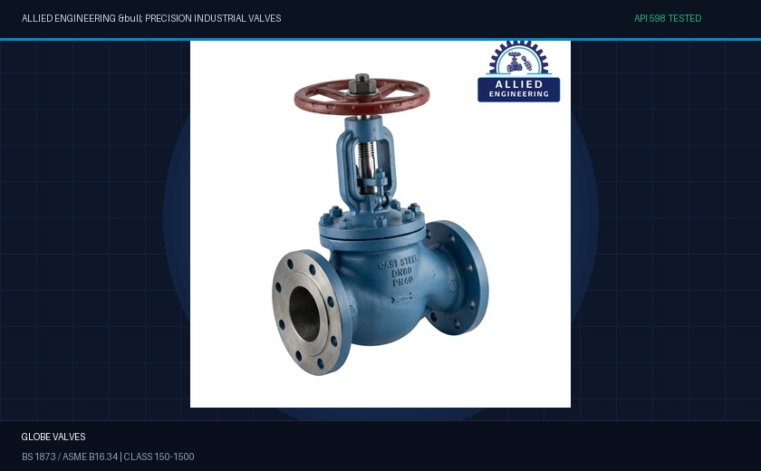
A Globe Valve is a linear-motion valve utilized primarily to stop, start, and regulate fluid flow. Unlike quarter-turn ball or butterfly valves, a globe valve’s closure member—termed a plug or disc—moves perpendicular to the plane of the valve seat.
The name “Globe” derives from the traditional globular outer body shape that houses the internal baffle dividing the valve chamber into two halves. This distinctive geometry forces the fluid to change direction (typically in an S-shaped flow path), generating a predictable pressure drop that enables proportional, fine-tuned flow control without causing severe cavitation or disc chatter.
Engineering Insight • Throttling Excellence
While gate valves must only be used fully open or fully closed to avoid high-velocity wire-drawing of the wedge, globe valves are deliberately engineered to operate reliably in intermediate throttle positions for extended duty cycles.
Key Design Configurations
Globe valves are manufactured in three primary body configurations tailored to specific piping geometries and allowable pressure drops:
- Z-Body Pattern (Straight-Through): The most common globe valve design. Fluid travels horizontally, makes two 90-degree turns across the horizontal diaphragm seat, and exits parallel to the inlet. Offers exceptional throttling precision.
- Y-Body Pattern (Oblique): The stem and seat are angled at approximately 45 degrees to the pipeline axis. This angled path straightens the flow trajectory, cutting the flow resistance (pressure drop) by over 50% compared to standard Z-bodies.
- Angle Body Pattern: Incorporates a 90-degree directional turn directly within the valve body, functioning simultaneously as an elbow fitting and a throttling valve, ideal for boiler feed lines and pump discharge systems.
Technical Specifications & Standards
| Parameter | Allied Engineering Standard Specification |
|---|---|
| Design & Manufacturing | BS 1873 / ASME B16.34 / API 602 (Forged) |
| Nominal Size Range | 1/2″ (DN15) up to 24″ (DN600) |
| Pressure Classes | ASME Class 150#, 300#, 600#, 900#, 1500#, 2500# |
| Body Materials | WCB Cast Carbon Steel, LCB Low Temp, CF8M Stainless, Alloy 20 |
| Trim Materials | API Trim 8 (Stellite / 13Cr), Trim 5 (Full Stellite Hardfaced) |
| End Connections | Flanged (RF/RTJ) ASME B16.5, Butt-Weld ASME B16.25 |
| Testing Standard | 100% Hydrostatic & Pneumatic Shell/Seat per API 598 |
Disc & Plug Designs for Varied Services
Depending on the media velocity and throttling requirements, globe valves utilize different plug geometries:
- Parabolic Plug (Throttling Disc): Features an elongated conical taper that provides linear or equal-percentage flow characteristics, essential for precision steam and boiler feed water modulation.
- Flat / Quick-Opening Disc: Delivers rapid opening with minimal stem travel, optimal for positive shutoff in intermittent batching operations.
- Needle Disc: Slender tapered needle designed for instrument metering, low-flow calibration, and sampling lines under high pressures.
Quality Assurance & API 598 Hydrostatic Testing
At Allied Engineering, every globe valve undergoes rigorous pressure testing on our calibrated hydrostatic test benches. We verify shell wall integrity at 1.5 times the rated working pressure and seat sealing leakage at 1.1 times maximum allowable pressure, ensuring zero-emission reliability in harsh petrochemical, power generation, and refining environments.